Designing the Brake Brackets
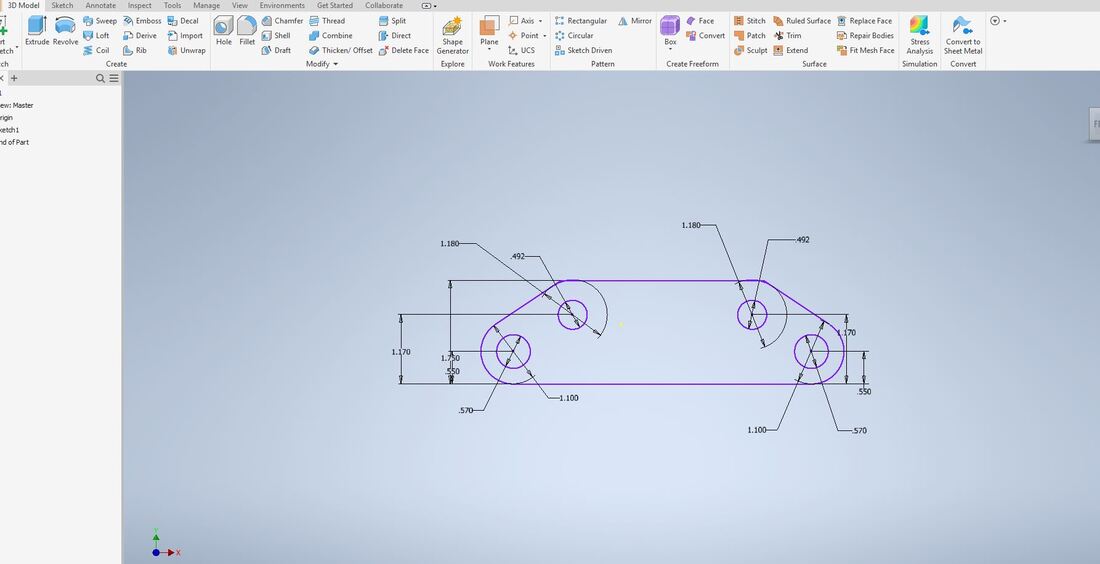
First I took the dimensions from the handout, and recreated the design in Inventor. Making this design required the tangent function, and the trim tool.
|
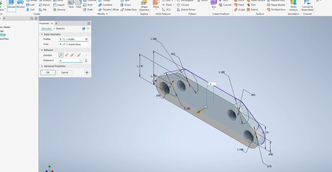
Next I extruded the shape by 0.4 to make it the size it should be.
|
This is the image from the first sketch of the bracket. Now onto the second image.
|
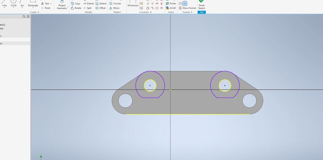
Now I started the second sketch to make the circles that go around the top circles. This step also required the tangent and trim tool.
|
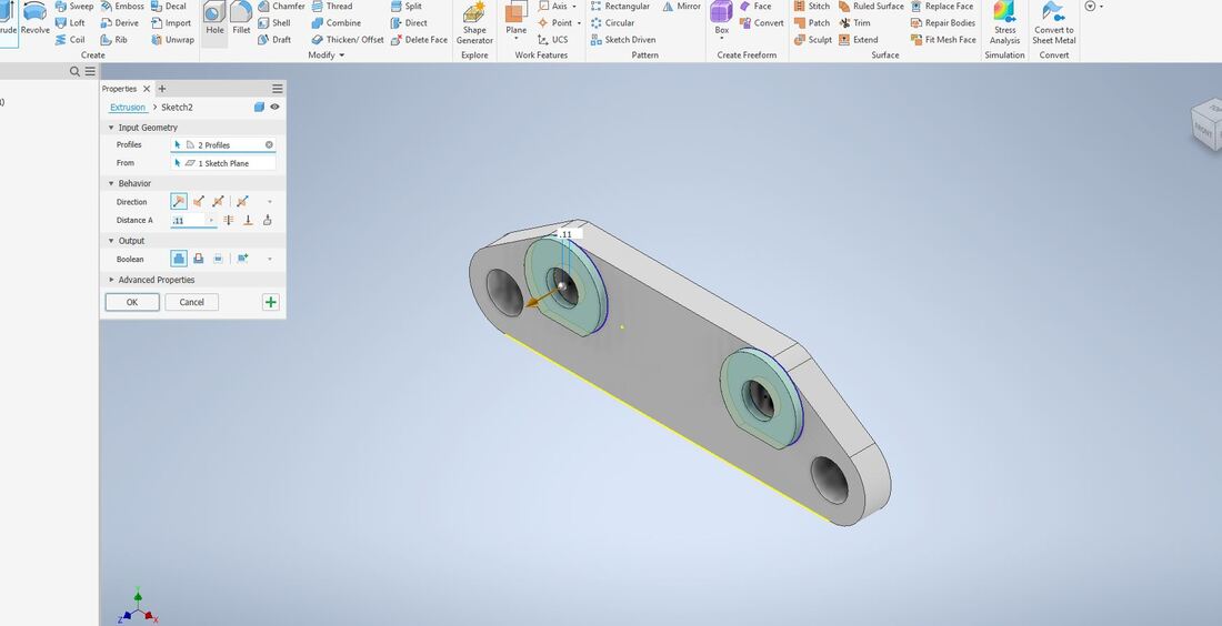
Now I did the second extrusion, so the bracket is almost complete.
|
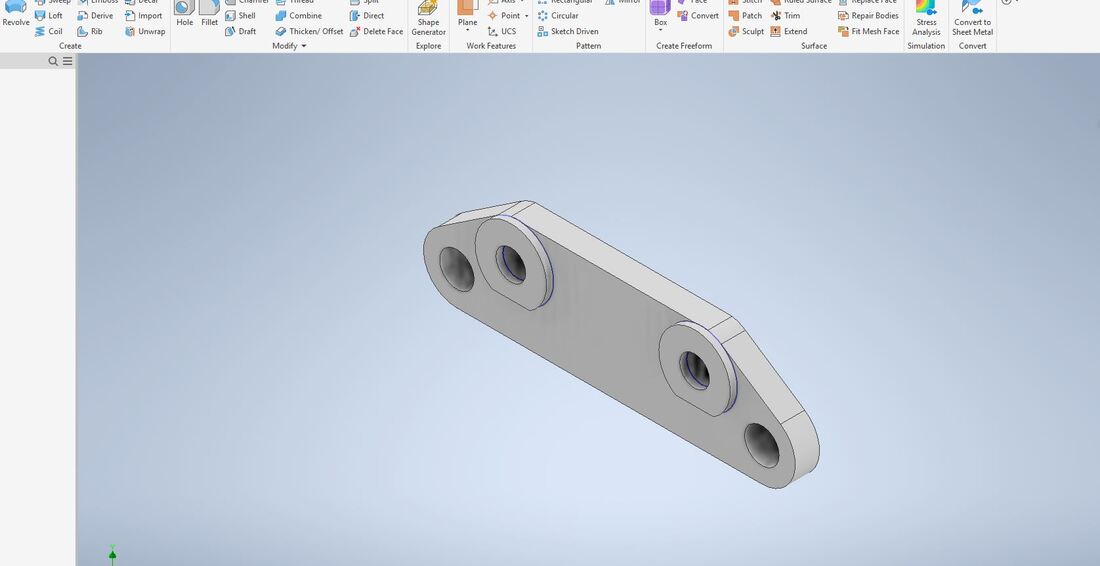
This is the final image of the brake bracket in Inventor.
|

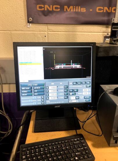
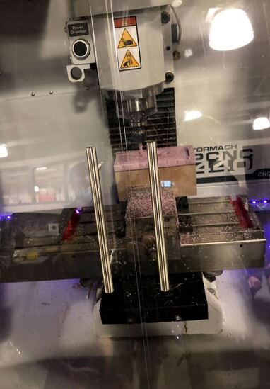
After creating the brake bracket in inventor, we would usually use Fusion 360 to simulate how the bracket would be cut out with the mill. This semester however we were short on time because of all the schedule changes due to corona virus. However we got a demo on how fusion and the mill would work. The images below are the CNC mill in progress making a demo brake bracket, and the computer set up with the g code which tells the mill how to cut out the bracket.
|
|
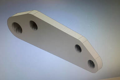
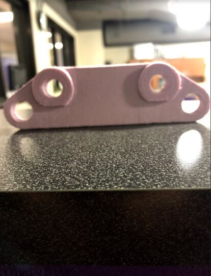
Final Brake Bracket
This is the image of the final brake bracket. I did not actually make this because of time, but its what the brake bracket would look like.
Final Thoughts
Throughout this process I learned how to make different shapes in inventor using the tangent tool. I also learned how to use Fusion 360 in the short demo. Even though I didn't use it, fusion seems like a very useful tool for the future. In addition to fusion 360 i learned how to use the CNC mill. This also seems like a cool things to use, and I can't wait to use it next year in Big Idea. Overall the brake bracket was fun to design in the short time we had.
